
scootergangbang
Members
-
Benutzer seit
-
Letzter Besuch
-
All very interesting. as a veteran of assembling small frame vespa engines, I can relate to the bearing failure problem in this thread. This problem started surfacing 2 years ago with FAG bearings. I would have had 5 failures over the last 2 years (on the drive side only), with exactly the same consequences as the picture. The problem is not caused by crankshafts being out of true, nor with case damage (damage caused by such things takes quite some time to appear, rather than just a few minutes running) the problem, (as I have been informed) is that even though bearing manufacturers claim otherwise, more and more bearings are being manufactured "off shore", and use inferior quality materials and machining processes. It used to be the case that if you wanted to find where a bearing was manufactured, you simply had to look on the bearing, and the country of origin was lazer engraved on the bearing. A few years ago,bearings started appearing with no country of origin on them (most where Indian origin), but I have started to see a trend for bearings to have Japan engraved on them, when infact, they come "a little further afield" The problem was such at one point, that a previous employer insisted I cleaned old original used Piaggio bearings out with brakecleaner and refit them, rather than use the faulty FAG bearings (which could not be returned for some strange reason) Like I say, I have seen this problem many times, and the fault is low quality rivets used in the cage consructions. " CAVEAT EMPTOR"
-
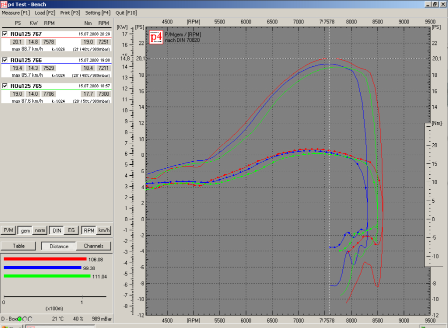
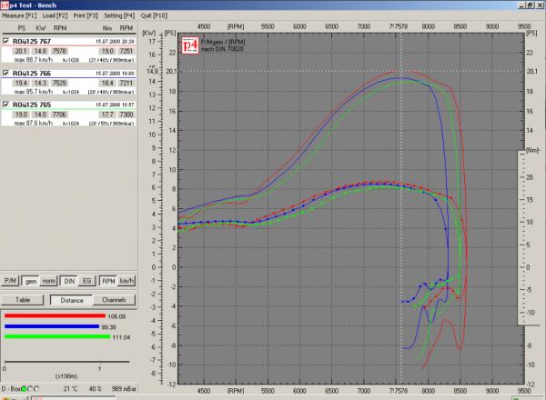
I am really surprised with the lower number your engine puts out, I am really curious, are you 100% certain that the bottom of the transfers of he liner have been un-shrouded as per my pictures?, also, what type of crankshaft are you using? is it a full circle? The reason I ask is that if you have a full circle, and the transfers are not un-shrouded as per my images, then that would explain the somewhat reduced power output you have. A "full circle" crankshaft has a primary compression ratio well over the maximum of 1.5:1, and with an exhaust with a baffle angle such as you have now, 1.35:1 is more suitable. With the cylinder you have, I was simply using normal "racing" cranks (they have less mass, and therefore increase the crankcase volume, thereby lowering the primary compression ratio, to something like 1.40:1, which is far more suitable, and reduces the dramatic pumping loss that a "full circle" crank causes. I really don't believe that you need a "short 4th" gear, I have never even used one, as I found them unnecessary if the engine was built correctly. You just need to increase your torque.... you have 16NM now, and I assure you 19NM is easy!
-
There is a small amount of room available in each cylinder for "blue printing" the cylinder, and I will be the first to admit, the cylinder with the graph shown was "blue printed" (as much as time areas and exhaust port matching go). With the handmade stuff, each one is going to be slightly different, but an experienced engine builder needs only to spend an hour finishing the ports and doing a bit of un-shrouding work to reach it's potential. The blueprinted cylinder's always had more PS and NM, (considerably so). The transfer angles are actually pretty good, as the ones I measured where all the same, as per my instructions. Something I always wanted to do was increase the transfer time area, but someone with just a modicum of knowledge on the subject will understand just how hard that is, while still retaining a working scavenge pattern. Last thing I remember was they where long stroking a cylinder.....I sometimes wonder how that went, particularly if it ran 2 rings.........
-
Valid points. There are resonance issues with that exhaust, due to its baffle angle, but I assure you, an half decent tuner can easily extract 24 PS from that cylinder and exhaust combo. I have briefly outlined what is required a few pages back. He mentions how well the "ss90 replica" goes, it has been modified as per my instructions....I should know..... I built the engine! I questioned the poster if the cylinder he has ,has been modified as per my instructions, he said it had, and I am surprised that it has less than 20PS, with the modifications as per my pictures, 22PS is the norm, some more work, 24PS The lower attachment posted is actually using the "Franz" exhaust,(I built the engine the day after the cylinders arrived from Vietnam, and the current exhaust arrived about a week later) but the engine had a slightly different set up than what is used with the "other" exhaust, but the cylinder was almost "plug and play"
-
Ich glaube, dein Stator ist ok, wenn wir jetzt Spannungen zwischen einer Spule und Masse, dann darauf hinweist, dass die Spannung Spule ist ok wäre. Wenn die Spannung nicht funktioniert, wenn Sie Ihren kabelbaumt dann haben Sie zwei possibilties 1) Der Kabelbaum ist an Masse kurzgeschlossen. (Einfache, entfernen Sie einfach den grünen Draht aus dem Lichtschalter, und trennen Sie das Kabel von der Grundplatte und testen Sie die Kontinuität zwischen dem grünen Kabel, die Sie aus dem Lichtschalter und Masse .. .. entfernt .. Sie sollten nicht connnected werden, wenn ja, haben Sie einen kurzen auf die Masse) 2) Die Masse der Kabelbaum ist falsch. Mit all die Kabel korrekt angeschlossen für die Kontinuität zwischen dem Motor und dem schwarzen Kabel überprüfen gehen zum Lichtschalter. Sie sollten über gute Kontinuität.
-
Vielleicht, wenn Sie das gelbe Kabel ablöten nur aus der unteren Spule in das Bild und das gelbe Kabel zu verlängern. Testen Sie, wenn Sie Spannung zwischen dem erweiterten gelben und dem schwarzen Kabel.
-
OK, Eine Frage, hat dieses System funktionieret für Sie vor, oder haben Sie erwerben die Zündung so? Wenn Sie eine 8 kabel Grundplatte wie dieser die zusätzlichen zwei kabel (gelb und grau) sind für ein separates Bremslicht und es hat eine eigene masse für die Spule. (Farbe grau bis masse, gelb bis Spannung) Vielleicht Spur der Spule mit den gelben und grauen Kabel, und ziehen Sie das gelbe Kabel, das extra hinzugefügt wurde. sehen, wenn Sie dann Spannung zwischen den gelben und grauen Kabel, dann auch zwischen der blauen und schwarzen kable . Das wird niemals Spannung zwischen den gelben kabel und schwarz, oder den grünen kabel und grau werden. Die 2 spulen haben seperate masse.
-
Normalerweise ist das Problem aus der Isolierung des Kabels auf der Grundplatte, eine Kurzschluß zu verursachen. Außerdem gibt es 2 Arten von Grundplatte, aus verschiedenen PK-Modelle, hat man insgesamt 6 Kabel, und das andere Ich denke, 8 Kabel. Wenn Sie solch hat 8 Kabel (die 2 zusätzlichen Kabel sind ein extra Spannung und unabhängige masse ......) Gibt es in Ihrem Stator haben insgesamt 6 Kabel, oder 8?
-
die 3 Kabel aus dem Stator (blau, schwarz, grün) Schwarz ist die masse Grün ist die Kill-Schalter Blau ist Spannung Zwischen den blauen und den schwarzen, sollten Sie haben (standgas) so etwas wie 15 oder 20 Volt, bei ca. 4.000 U / min sollte es so etwas wie 45 Volt sein. Dies wird mit-out Anschluss an den Spannungsregler. Wenn Sie die Leitungen an den Spannungsregler nach der shaltplan, dann 12V zwischen dem grünen Kabel und masse haben sollte. Wenn du haben keinen mulitimeter für richtige Spannung zu testen, testen, ob Sie überhaupt keine Spannung haben, können Sie (bei laufendem Motor) schnell touch das blaue Kabel und das schwarze Kabel zusammen, sollten Sie eine dicke, fette blaue Funken . Dies zeigt, haben Sie Spannung aus dem Stator
-
if you checked it, then that's all good.
-
Are you certain it is completely finished as per my pictures? Have you checked?
-
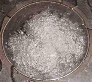
Ha, no not quite. A closer look will show you it's a test rig to flow water and compressed air, through the transfer ports into the cylinder (with a clear sheet of perspex bolted to the top), in an attempt to dynamically map the scavenge patterns, not really very successful, and I found an easier way with out all the effort.
-
Here is an old picture of some early work with scavenge patterns that I applied to the cylinder.....the tests where inconclusive, but the idea was good.
-
My early designs simply relied on 2 small holes on the exhaust side of the piston, in line with the bridge (such as used on 125 GP bikes). Subsequent tests showed this was not needed. There is a lot of cast iron on the bridge, and, yes, very little aluminium, however, I have not experienced a failure, and it works as it is. I spent a lot of time ensuring the exhaust temperature was as low as I could get it.....that is why the exhaust port is not as wide as it could go, it reduces the amount of localised heating of the exhaust side of the piston crown, as well as the exhaust port/bridge area. If someone felt the need, sure, 2 x 2mm holes drilled vertically in line with the bridge will suffice.
-
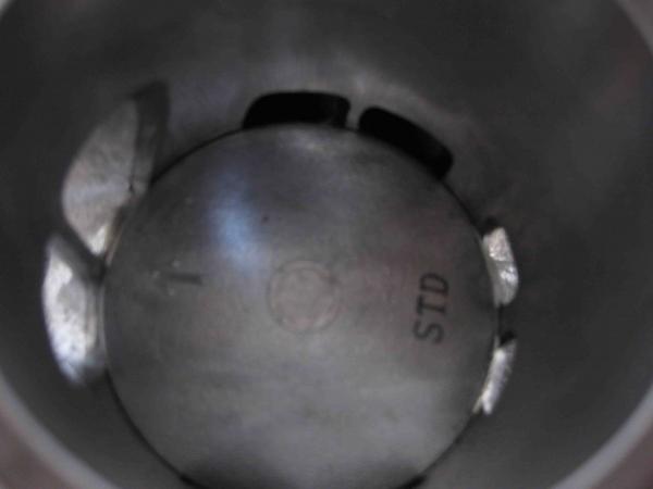
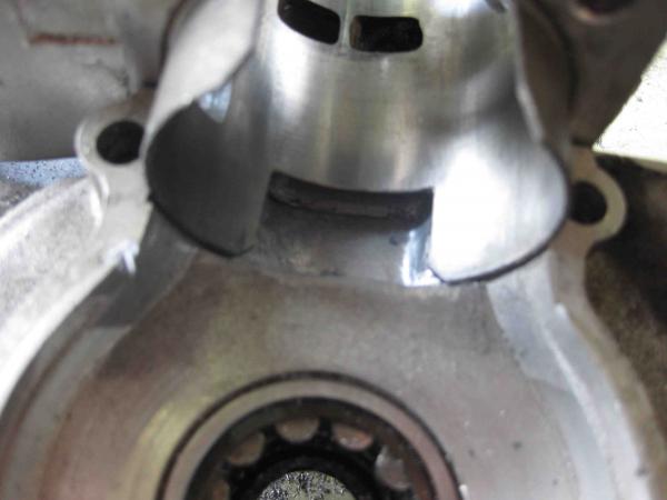
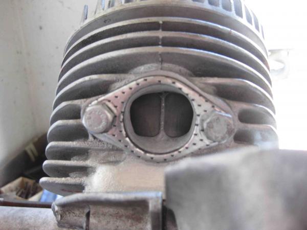
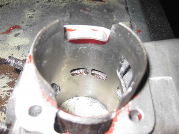
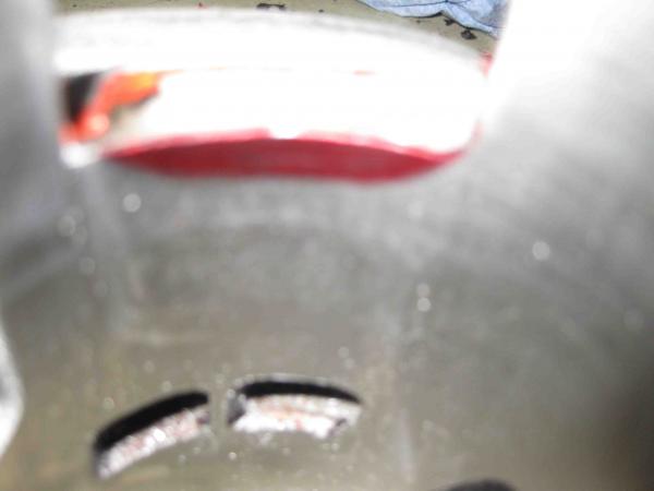
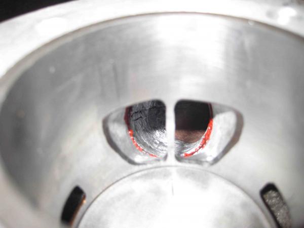
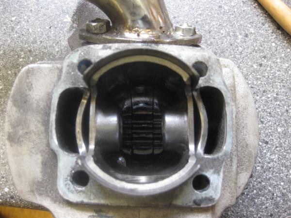
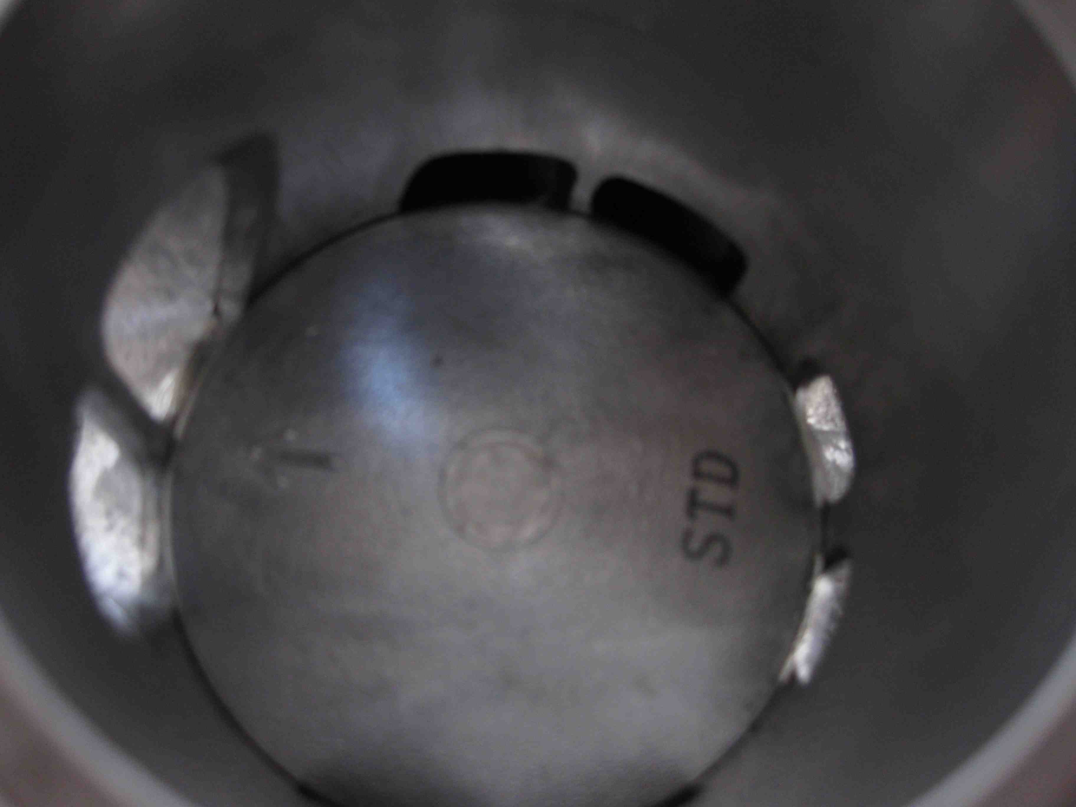
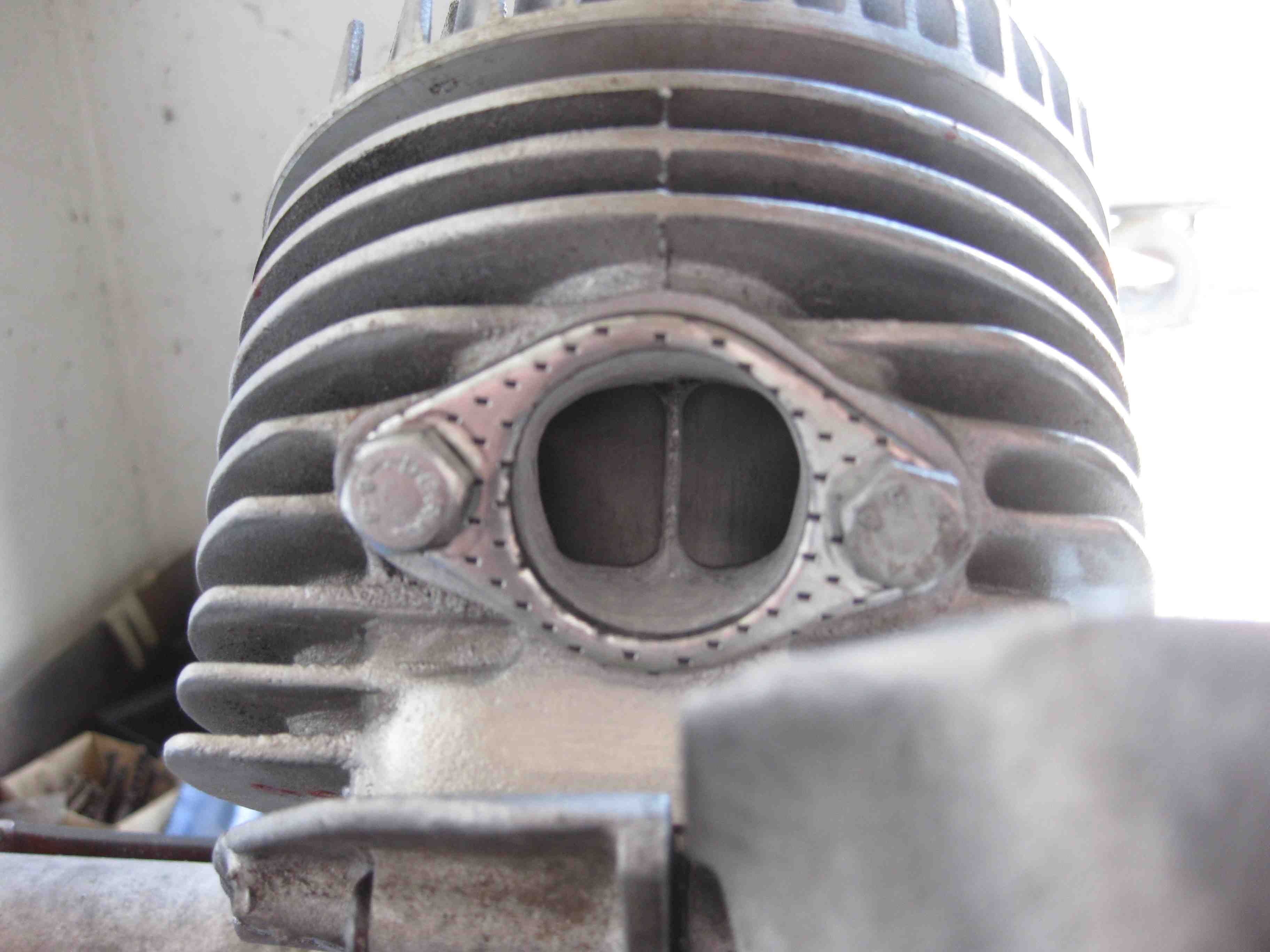
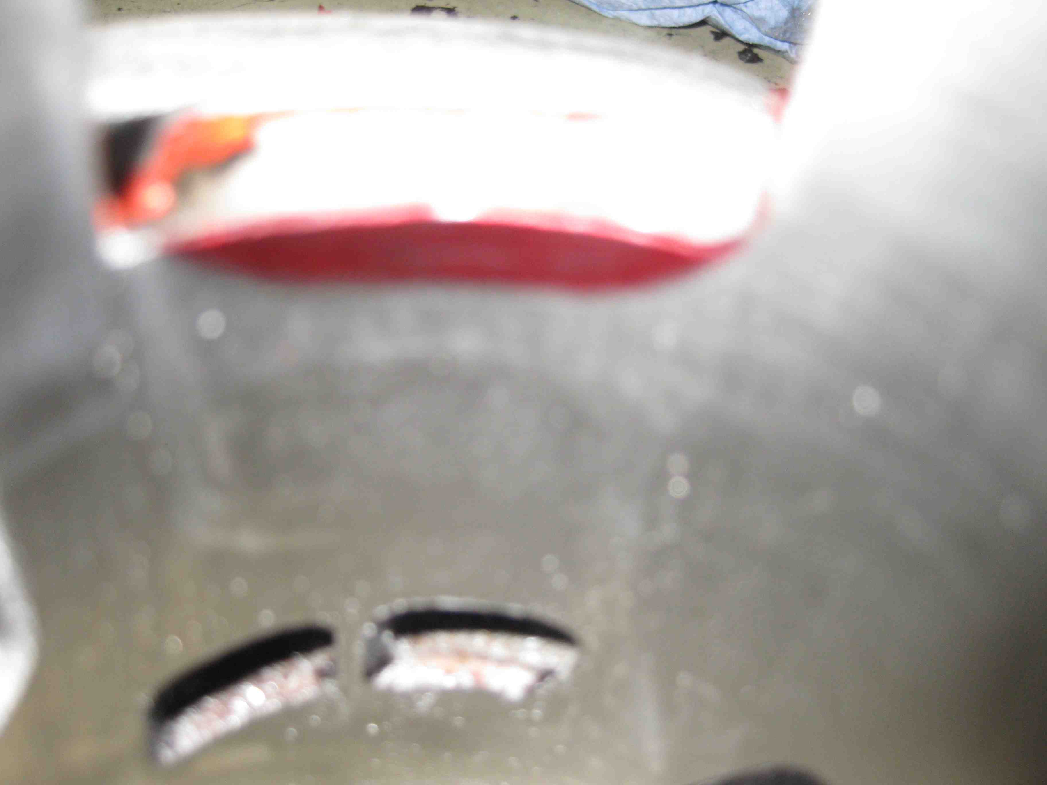
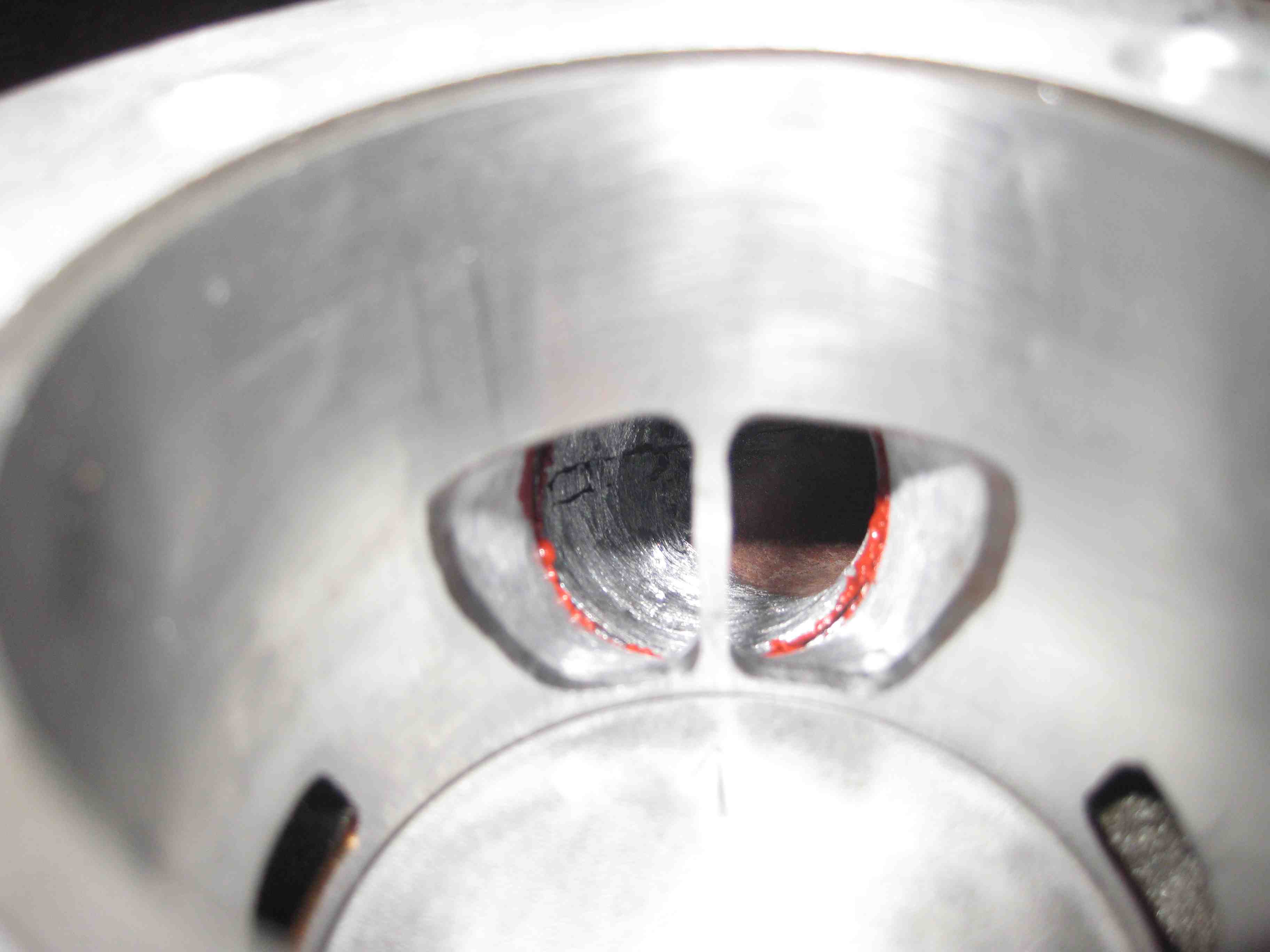
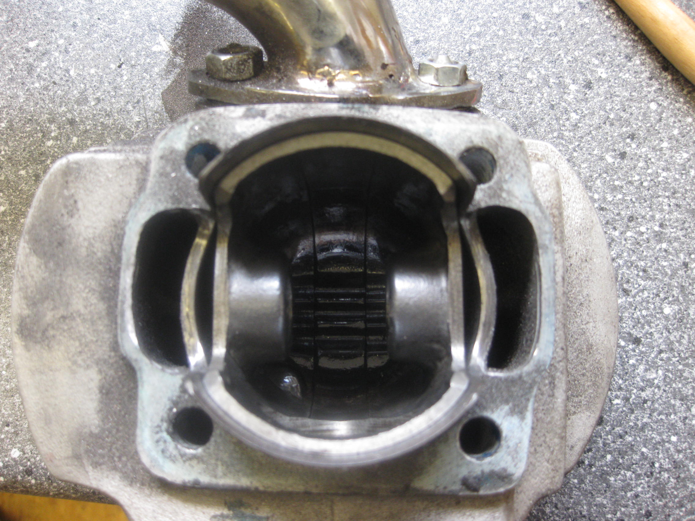
O.K When I first designed the cylinder that "the factory" sell (and claim they designed themselves, which is not true) I was limited with budget and resources. The cylinder was made in Vietnam, and I could not control either quality, nor that they would themselves steal my work. The piston is the limiting factor in all development (the piston is from a 1998 Suzuki RG150), and requires boring the gudgeon pin to suit the Vespa (they seem to be able to do that quite well in Vietnam) The current cylinder exhaust time/area is pretty much what you need, as is the blowdown time. Using a slightly modified Malossi cylinder head, the corrected compression ratio is well with-in established safety limits. As the original cylinder I was developing had limitations (due to the "CVF" ports, which made removal of material around the cylinder spiggot neigh on impossible), I had to find an alternative way of more effectively scavenging the crankcase at BDC,(the shrouding of the transfer cut outs in the piston was unbelieveable) on the test cylinder, I achieved this by using the boost port at BDC as a transfer port, via 2 holes in the piston, just below the crown, on the inlet side,which, at BDC lined up with the boost ports in the reed block. relying on the expansion chamber to keep the top reed petal open. Nothing new, or ground breaking. Coupled with removing as much material from the spiggot area as I felt safe. I drew some basic pictures of a scavenge pattern (again, nothing ground breaking....) on a piece of paper and gave it to the Vietnamese chap who owned the sweat shop charged with production, and explained which dimensions where the most important (for example, giving a height from TDC for the exhaust port, along with a width to exactly follow, allowed for the corrected compression ratio and exhaust time areas to be as close to what it needed to be, considering that they are just "hand workers", nothing more. What seemed like an eternity later, the new cylinder arrived, again, the cylinder heads where rubbish (full of porosity), so the venerable Malossi head was pressed back in to service. PIcture 1) The basic layout Picture 2) The cylinder foot as it comes "plug and play" (so to speak) Picture 3) A finished exhaust port from the outside Picture (s) 4) & 5) The area's of the liner marked that need to be removed from all the cylinders, enabling more complete crankcase scavenging, due to the shrouding of the transfers. Picture 6) Exhaust port from the inside. PIcture 7) unshrouding on an early (1st series) cylinder I did experiment on the new cylinder with again, using the boost port as a transfer port, and was rewarded with power gains, but I felt that with a steel lined, low quality aluminium such as is used in this cylinder, I needed a small amount of fuel to remain under the piston to aid cooling, and that for customers, reliability was more important than squeezing the last drop. If someone has a det sensor and an EGT, it would be worth experimenting with further, and perhaps some more testing with cylinder heads....I have a few designs....